Issue 23 June 2026 Two new papers have been included in this issue of The Micrometer. The first describes the design and construction of an automatic radial feed facing head suitable for use on a Myford lathe and light vertical milling machine, and the second a sensitive drilling attachment suitable for a lathe with a No.2 Morse taper tailstock.
The facing head requires the cutting of a scroll (as used in 3-jaw self-centring lathe chucks) and some familiarity with epicyclic (sun and planet) gearing, and the sensitive drilling attachment requires a rack and pinion to be cut. With a little ingenuity, all these operations can be undertaken in the home workshop using the equipment for which the attachments are intended.
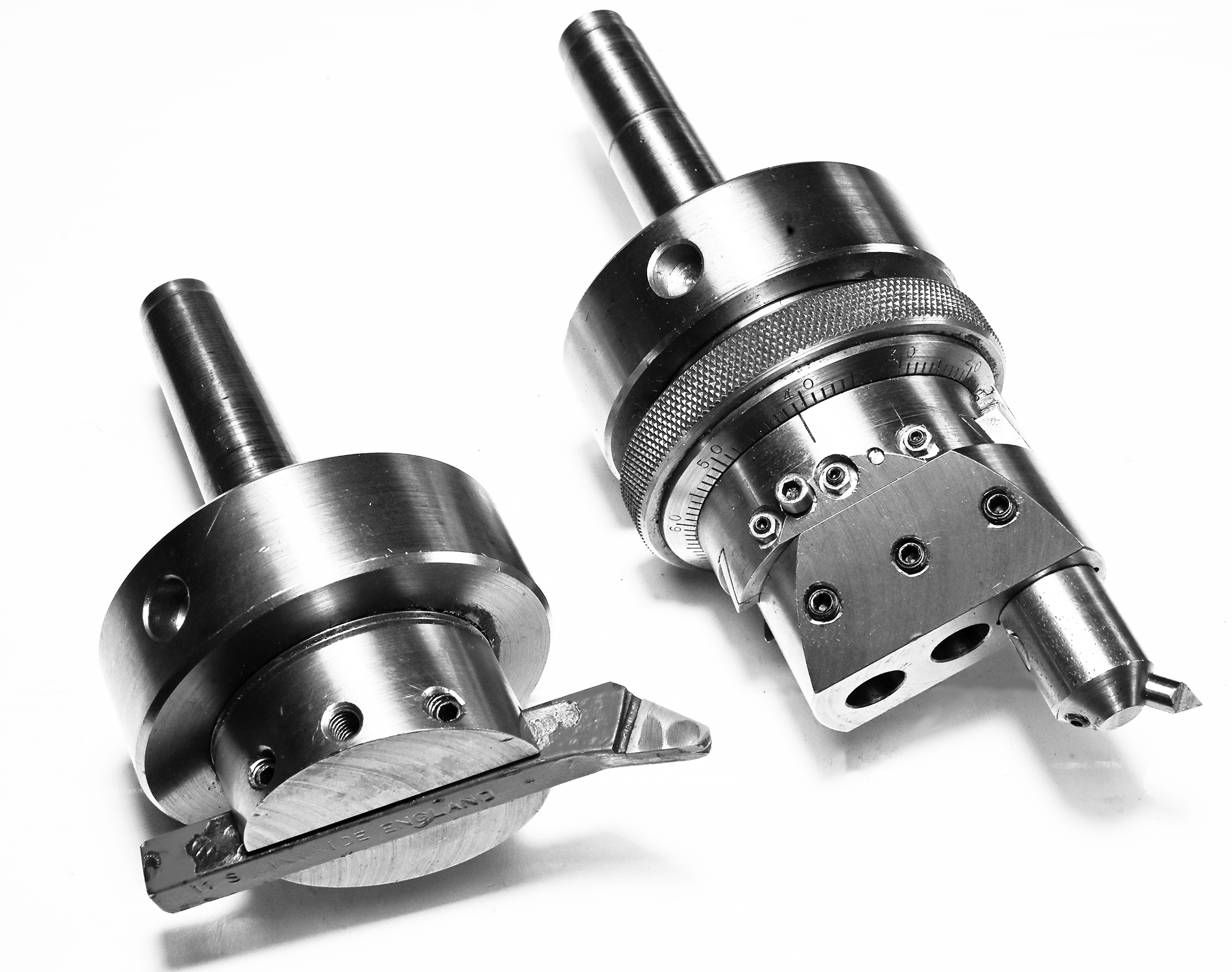
No.2 Morse taper facing tools (December 1989)
A flycutter and an automatic radial feed boring and facing head
One of the principal operations in the small workshop is machining a plane surface (flat face) on work that cannot be easily held in a lathe chuck. Holding the work on the lathe cross-slide or milling machine table, the simplest tool to enable this to be undertaken is the flycutter. But where the work also needs to be faced radially, a more sophisticated automatic radial feed offers considerable advantages.
Suitable for holding in a No.2 Morse taper spindle, this paper presents the author's design and accompanying constructional notes for both tools. Making use of epicyclic gearing and a scroll plate (similar to that found in self-centring 3-jaw lathe chucks), the latter requires some sophisticated machining techniques that should be viewed as a challenge rather than an obstacle.
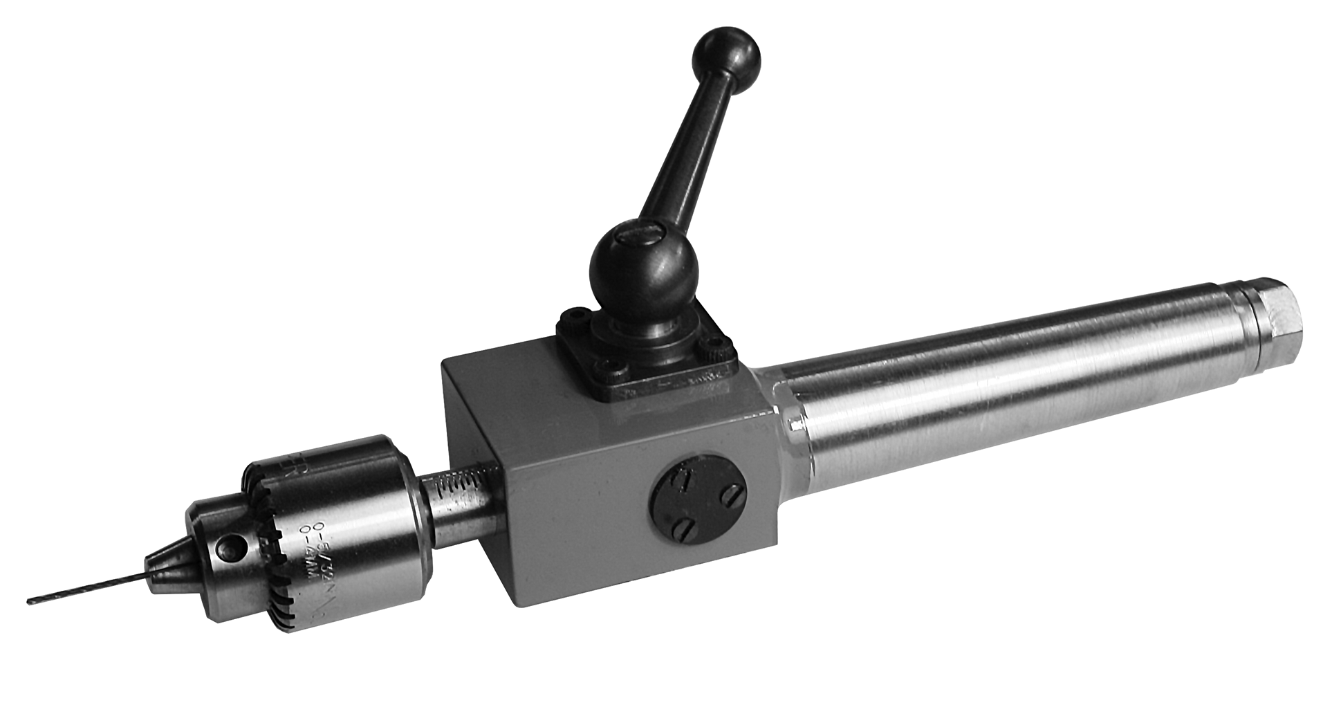
A tailstock sensitive drilling attachment (February 2017)
Suitable for drilling 0 to 4 mm diameter holes from the lathe tailstock
Finding the traditional linkage-based lathe sensitive drilling attachment both cumbersome and ugly, the author designed and constructed a rack feed alternative. In use with its minimal backlash and feed sensitivity, it as been found especially suitable for drilling 1.0 mm diameter and smaller holes not uncommonly found in horological work.
Drawn with a No.2 Morse taper, it requires a 1.0 mod rack and 12 tooth meshing pinion to be cut, but with care and precision in its manufacture, it is not a difficult constructional project for the reasonably competent machinist.
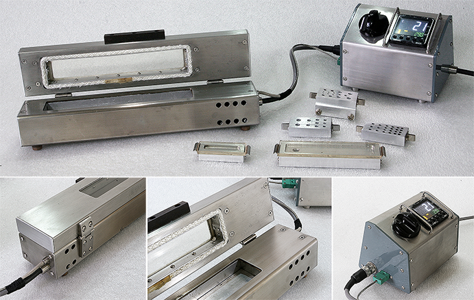
After a brief introduction to methods of heat bluing steels, the author comments on the dependency of the achieved colour on both temperature and ‘soaking’ time at this temperature before describing the design, manufacture and uses for an electrically-heated bluing box under digital temperature control.
Components ranging from 15 mm long clock hands and small screws through larger instrument hands right up to machine toool ball handles have been successfully heat blued in the PID-controlled bluing box. Fully illustrated with photographs and schematic drawings, there is no single solution to all decorative bluing issues, and the bluing box is not entirely without limitations in its performance. The paper concludes that it is a valuable, mess-free addition to the workshop, and those needing primarily to colour steel components may wish to consider its merits.
* PID: A Proportional-Integral-Derivative digital controller capable of maintaining the bluing box hotplate temperature to within ±1°C of the Set Value (SV).
Readers are invited to share their own experiences with decorative heat bluing of steel and, in particular, their experiences with a PID-controlled bluing box.
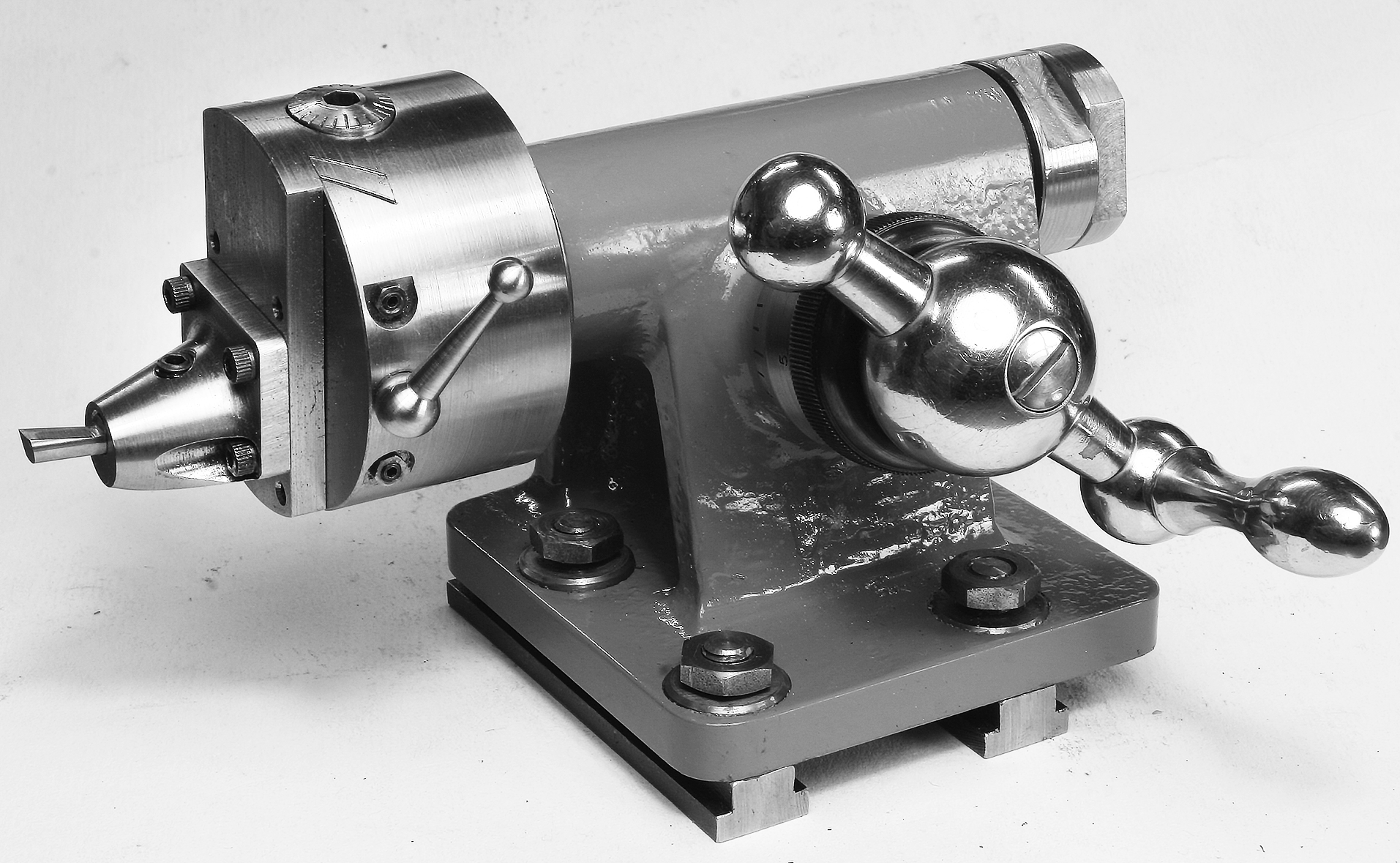
A spherical turning attachment (December 2021)
The design and construction of an attachment suitable for the Myford Super 7 lathe
The ability to make ball handles is essential for the serious workshop accessory constructor, and the design and full engineering drawings here presented bolts directly to the cross-slide so making it far sturdier than a toolpost mounted variant.
It has also been used to cut 'spiders' for the spherical centres of Hooke universal joints.
The tool is fitted to an adjustable block, and the feed is provided by rotary handle via a 12:1 worm drive. The cast iron base is a modified casting for the Geo.
H Thomas dividing head tailstock, and the worm and worm wheel are proprietary items.
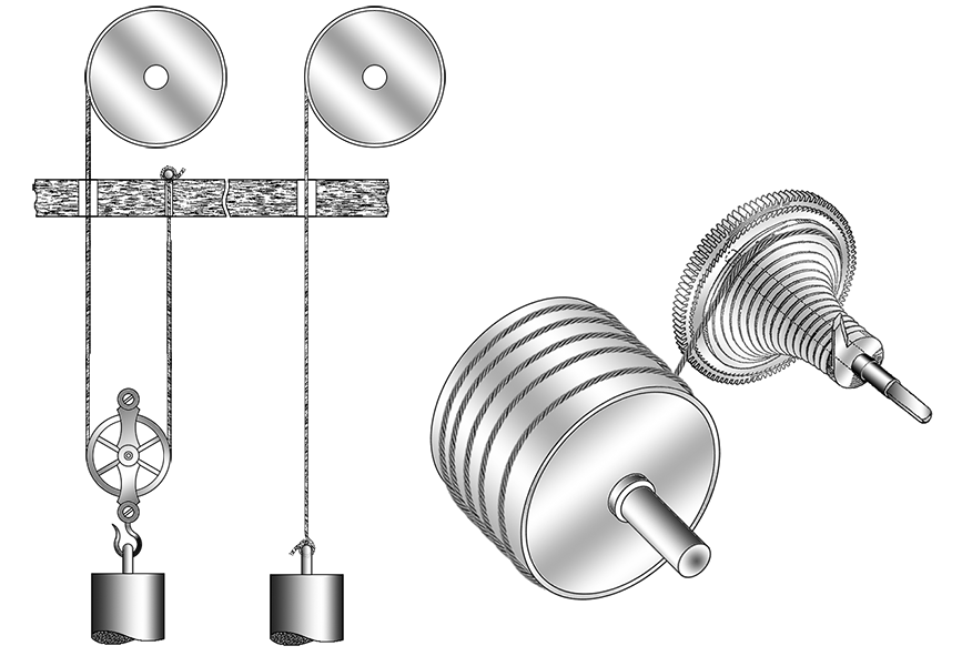
An exploration of driving lines for weight-driven and fusee clocks
Clock lines have received little engineering assessment in the horological press, with much opinion being based on received wisdom and what has been found to work.
Part 1 investigates the different types of construction of stranded steel and brass/bronze lines. Part 2, which is perhaps the most significant, reports on the author's creep trials on natural gut and nylon-6 synthetic lines conducted over a 6-month period and their extrapolation to a 20-year in-service life. Part 3 discusses the possible implications of creep on non-metallic weight-driven and fusee lines before drawing together a few overall remarks. To complement the three part paper, an Appendix has now been added describing the manufacture and testing of crimps for eye splices.
Readers are invited to comment on the papers and make any recommendations leading to a greater validation of the author's concluding remarks.
A balance vibrating tool (October 2014)
A year 2/3 project for students of horology
The author presents the design and construction of a balance vibrating tool suitable for second year clock and watch students or those with a good understanding of workshop and horological practices. Not only does the construction of this tool provide an advanced project for students but also results in a tool that enables a quick selection and adjustment of a balance spring in subsequent spring-balance clock and watch repair work.
Suitable for both watch and clock pathway students, all standard parts are available from horological requisites suppliers. A degree of skill is needed for its successful completion, and any person achieving success should not only be congratulated but can also consider him or herself well on the way to becoming a skilled craftsperson.
The Micrometer has been developed for use on a desk-top computer, W3C coding being written in Adobe Dreamweaver and validated in the Safari browser running on a Mac Studio desktop. Comments on articles appearing in The Micrometer are invited. In the first instance, the author asks that readers wishing to make comments introduce themselves via the E-mail address below (this is a composite image file used for the avoidance of spam, so cannot be double-clicked and will need to be typed into the reader's E-mail application).